Today I’m writing about a small project I made to test some peripherals of the STM32 microcontroller.
In this case, I’m using an I2C OLED display and two of the board’s ADCs. The goal is to display the input signals on the screen as if it were an oscilloscope in XY mode.
Here’s a demo video:
For this, this library from Github will be included.
After that, the ADCs (same configuration) and the I2C interface will be configured.
static void MX_ADC1_Init(void)
{
/* USER CODE BEGIN ADC1_Init 0 */
/* USER CODE END ADC1_Init 0 */
ADC_ChannelConfTypeDef sConfig = {0};
/* USER CODE BEGIN ADC1_Init 1 */
/* USER CODE END ADC1_Init 1 */
/** Configure the global features of the ADC (Clock, Resolution, Data Alignment and number of conversion)
*/
hadc1.Instance = ADC1;
hadc1.Init.ClockPrescaler = ADC_CLOCK_SYNC_PCLK_DIV2;
hadc1.Init.Resolution = ADC_RESOLUTION_12B;
hadc1.Init.ScanConvMode = DISABLE;
hadc1.Init.ContinuousConvMode = DISABLE;
hadc1.Init.DiscontinuousConvMode = DISABLE;
hadc1.Init.ExternalTrigConvEdge = ADC_EXTERNALTRIGCONVEDGE_NONE;
hadc1.Init.ExternalTrigConv = ADC_SOFTWARE_START;
hadc1.Init.DataAlign = ADC_DATAALIGN_RIGHT;
hadc1.Init.NbrOfConversion = 1;
hadc1.Init.DMAContinuousRequests = DISABLE;
hadc1.Init.EOCSelection = ADC_EOC_SINGLE_CONV;
if (HAL_ADC_Init(&hadc1) != HAL_OK)
{
Error_Handler();
}
/** Configure for the selected ADC regular channel its corresponding rank in the sequencer and its sample time.
*/
sConfig.Channel = ADC_CHANNEL_1;
sConfig.Rank = 1;
sConfig.SamplingTime = ADC_SAMPLETIME_3CYCLES;
if (HAL_ADC_ConfigChannel(&hadc1, &sConfig) != HAL_OK)
{
Error_Handler();
}
/* USER CODE BEGIN ADC1_Init 2 */
/* USER CODE END ADC1_Init 2 */
}
static void MX_I2C1_Init(void)
{
/* USER CODE BEGIN I2C1_Init 0 */
/* USER CODE END I2C1_Init 0 */
/* USER CODE BEGIN I2C1_Init 1 */
/* USER CODE END I2C1_Init 1 */
hi2c1.Instance = I2C1;
hi2c1.Init.ClockSpeed = 100000;
hi2c1.Init.DutyCycle = I2C_DUTYCYCLE_2;
hi2c1.Init.OwnAddress1 = 0;
hi2c1.Init.AddressingMode = I2C_ADDRESSINGMODE_7BIT;
hi2c1.Init.DualAddressMode = I2C_DUALADDRESS_DISABLE;
hi2c1.Init.OwnAddress2 = 0;
hi2c1.Init.GeneralCallMode = I2C_GENERALCALL_DISABLE;
hi2c1.Init.NoStretchMode = I2C_NOSTRETCH_DISABLE;
if (HAL_I2C_Init(&hi2c1) != HAL_OK)
{
Error_Handler();
}
/* USER CODE BEGIN I2C1_Init 2 */
/* USER CODE END I2C1_Init 2 */
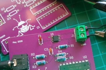
}The most important part is adapting the audio jack output to the ADC inputs, you need to get rid of the negative part of the signal.
And here’s the code for main.c:
/* USER CODE BEGIN PV */
#define CLEAR_INTERVAL 200
/* USER CODE END PV */
..........
...
.
/* Private includes ----------------------------------------------------------*/
/* USER CODE BEGIN Includes */
#include "ssd1306.h"
#include "ssd1306_fonts.h"
#include "math.h"
#include <stdio.h>

/* USER CODE END Includes */
.........
...
.
/* Private user code ---------------------------------------------------------*/
/* USER CODE BEGIN 0 */
#define NUM_SAMPLES 128
uint16_t adc1_buffer[NUM_SAMPLES];
uint16_t adc2_buffer[NUM_SAMPLES];
/* USER CODE END 0 */
.........
...
.
  /* USER CODE BEGIN 2 */
  ssd1306_Init();
  ssd1306_Fill(Black);
  ssd1306_SetCursor(2, 10);
  ssd1306_WriteString("Cascajo", Font_11x18, White);
  ssd1306_SetCursor(2, 30);
  ssd1306_WriteString("Labs", Font_11x18, White);
  ssd1306_UpdateScreen();
  /* USER CODE END 2 */

  /* USER CODE BEGIN WHILE */
  HAL_ADC_Start(&hadc1);
  HAL_ADC_Start(&hadc2);

  ssd1306_Fill(Black);
  uint32_t counter = 0;
  uint16_t valL = 0;
  uint16_t valR = 0;
  while (1)
  {
	    // Read L (ADC1)
	    HAL_ADC_Start(&hadc1);
	    if (HAL_ADC_PollForConversion(&hadc1, 1) == HAL_OK) {
	        valL = HAL_ADC_GetValue(&hadc1);
	    }
	    HAL_ADC_Stop(&hadc1);

	    // Read R (ADC2)
	    HAL_ADC_Start(&hadc2);
	    if (HAL_ADC_PollForConversion(&hadc2, 1) == HAL_OK) {
	        valR = HAL_ADC_GetValue(&hadc2);
	    }
	    HAL_ADC_Stop(&hadc2);

	    // OLED
	    int x = ((int)valL - 1400) / 32 + 64;
	    int y = 32 - ((int)valR - 1300) / 32;

	    if (x >= 0 && x < 128 && y >= 0 && y < 64) {
	        ssd1306_DrawPixel(x, y, White);
	    }

	    counter++;
	    if (counter >= CLEAR_INTERVAL) {
	        ssd1306_UpdateScreen();
	        ssd1306_Fill(Black);
	        counter = 0;
	    }
    /* USER CODE END WHILE */

    /* USER CODE BEGIN 3 */
  }
  /* USER CODE END 3 */
These values (1400 and 1300) are used to center it on the screen and were determined by simple visual adjustment.
With the same logic, you can create other simple projects that use different I2C devices, such as a gyroscope — like in this demo video: